Roll Gap Adjustment System for Straightening Machines
In the metallurgical finishing line, the role of the straightener is, on the one hand, to level the surface of the strip within a certain elastic deformation range to meet the user‘s requirements; on the other hand, to transport the strip in synchronization with other equipment of the unit. It is one of the most critical parts to ensure the quality of the product. Therefore, it is very important to ensure its normal operation to improve the safety production and product quality of the unit.
Process requirements and control principle
1. Process requirements
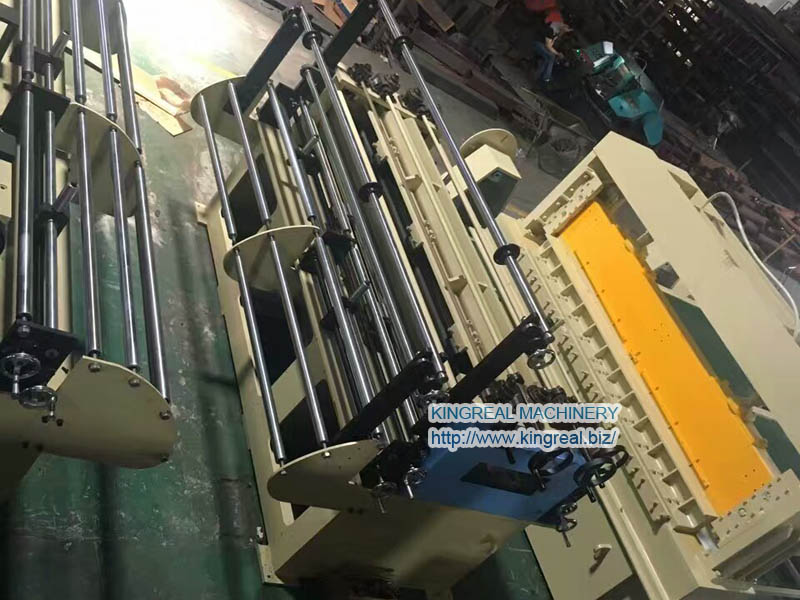
The straightening machine consists of 17 working rolls, 8 upper rolls and 9 lower rolls, the upper rolls are fixed and the lower rolls are controlled by the roll gap control system to control their lifting and lowering to complete the straightening of the strip surface. The process requires that the control system should be able to set and save the straightener roll shape, allowing the operator to change the position of the inlet or outlet rolls by clicking on the graphic position on the touch screen, which can be adjusted individually or together.
The system maintains the set value of the rolls throughout the production process, ensuring a constant roll shape regardless of the force applied to the rolls.

2. Control principle
The control system mainly consists of the following parts: Mac apple machine, USC13″ color touch screen, 68000 controllers, etc.
The working principle of the system is to input the requested data such as the amount of pressure down and compensation value from the touch screen of the Mac machine, which is transmitted to the 68000 serial interface modules through the serial cable, and the speed of digital change can be adjusted by a few thousandths of an inch/second. The feedback signal from the 0~5K position sensor is transmitted to the A/D converter module via the A/D cable and sent to the 68000 CPU via the parallel data bus for comparison with the given depression value to form a closed loop control.
After the comparison signal is amplified, it is output from the I/O module to the servo valve to control the movement of the hydraulic cylinder. The calculation of the feedback amount is completed by the 68000 controllers, and the range of the previous feedback value is calculated by the formula: 0~4095. From this position amount, the feedback position of the roll is determined according to the distance between the roll and the entrance to the roll pitch.
In order for the 68000 controllers to confirm the feedback value, an initial value must be given as a position reference by calibrating the straightener.

System Hardware Design
By the process and working principle, the hardware options of the control system are as follows: 68000 controllers from UNICO, equipped with 32-bit CPU module for arithmetic processing, 256KRAM, 256KEPROM; 12-bit A/D conversion module with conversion speed less than 200μS. USC 13″ touch screen with resolution of 800X600 and RS485 for interface.
The position sensor is KTR linear displacement sensor from BEI DUNCAN, with linearity error 0.1% and repetition accuracy 0.013mm. MAC computer is Mac Mini, GMA950 graphics chip.
System Software Design
According to the specific control functions to be realized by the straightening machine, the whole control program is divided into several control modules: it consists of a main program, six subroutines and an interrupt program. The functions of each program are as follows.
(a) Main program: initialization of program variables, initialization of the high-speed counter (for the input of the speed measuring rotary encoder) and timer (for the interrupt program), call of subroutines 1, 2, 5.
Subroutine 1: initialization of the touch screen and the command word processing subroutine corresponding to the touch screen keys.
Subroutine 2: Feeding speed control subroutine, according to the two states of "pointing feeding" and "automatic feeding" to achieve the upper and lower rows of rollers feeding speed control.
Subroutine 3: Calculate the reading value of the position sensor when the lower row of rollers is up against the rollers. That is, the value of the position sensor at the position reference plane.
Subroutine 4: subroutine of roll seam control, which realizes roll seam control according to the three states of "lowering roll", "leaning roll" and "seam control".
Subroutine 5: Judging whether the parameter settings are reasonable, including the inlet roll seam value, the outlet roll seam value, the speed of the roll, the proportional control coefficient of the front and rear roll seams, the static zone tolerance, the input threshold of the servo amplifier, etc.
Subroutine 6: Calculation of the voltage output value of the controller based on the position deviation and feedback control, these voltages are input to the servo amplifier controlling the front and rear roll seam; Interrupt program: Calculation of the ideal and actual values of the roll seam and the feed speed, and checking whether the roll seam is over-compensated, re-initialization of the timer.
Operation analysis
The system is initialized before running, and parameters closely related to the amount of position are set: distance from the entrance to the roll is 10 inches, roll-to-roll spacing is 13 inches, sensor length is 2 inches, open position limit is 1 inch, press down position limit is -0.1 inch, threading position is 0.4-inch, static zone tolerance is 0.001-inch, maximum increment of deviation is 0.005 inch/second, minimum increment of deviation is 0.001 inch/second. When the machine is running at 260m/min, the leveling accuracy is within 0.1mm. During the production process, there were two main problems with the system.
(1) After starting the Mac computer, the production operation screen could not be accessed. This means that the Macintosh, the operating system of the Mac computer, could not find the application and the computer encountered problems in identifying the SCSI device. This determines that the system software failure or hard disk damage and loose interface plugs.
First check the interface plug, no abnormalities; then use the tool disk to boot, still cannot enter the system, which indicates that the hard disk is damaged. After replacing the hard disk, formatting and reinstalling the system software and applications, the operation is normal.
(2) After the strip has been straightened by the straightener, the plate shape has not been well improved. According to the system working principle, the causes of this phenomenon may be: ① solenoid valve or position sensor damage; ② abnormal 68000 controllers; ③ Mac Apple computer failure; ④ incorrect position reference, etc.
Check the solenoid valve, the coil is powered, magnetic, which indicates that the solenoid valve is normal, while indicating that the 68000-controller rack of I/O modules corresponding to the channel are good. Then check the sensor, measured its voltage value from 0 to 5VDC change, the range is correct, indicating that the sensor is also no problem.
Then check the 68000 controllers, the signal indicators are on, and 15VDC, 5VDC values are normal, indicating that the 68000 controller CPU and other modules are not a problem. Then check the Mac computer, its application program, system software is running normally, select the diagnostic program to monitor the relative position of the hydraulic cylinder changes, the action is correct. Recalibrate the straightener roll seam value, determine the new benchmark, and run the machine through the strip, the strip surface is leveled well.
In addition, to improve the system response speed and further improve the quality of plate shape control, the Mac Apple computer was upgraded and the network interface tool TERM program was rewritten to allow the 68000 controllers to communicate properly with the computer.


 +86-137 0285 5825
  sales@kingreal.org
 jet-clima