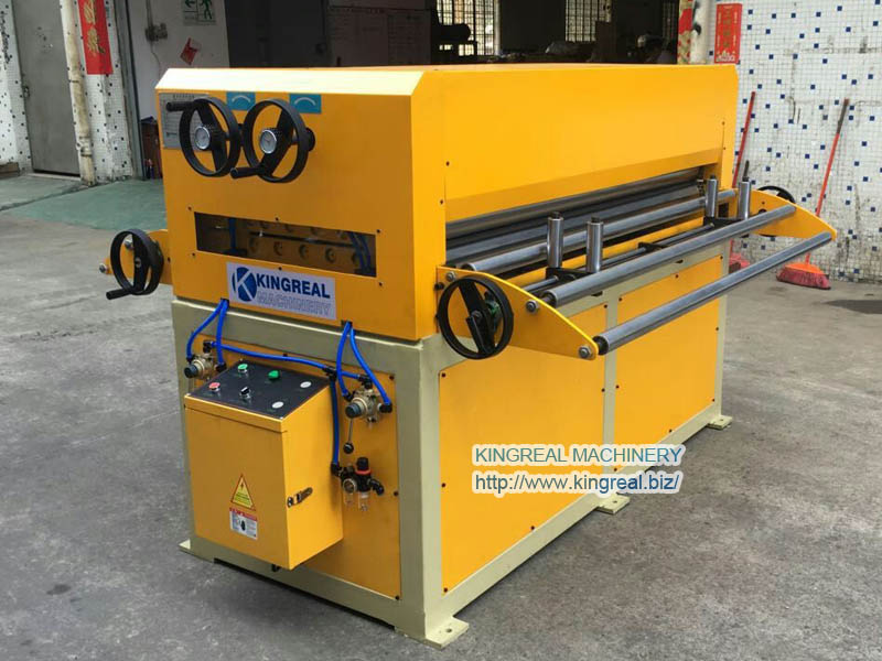
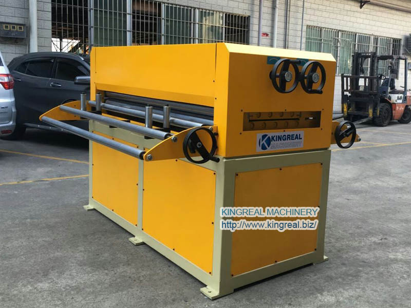
Principle Of Straightening Machine Structure
Tensile bending straightening machine (referred to as "tensile straightening machine") is a new type of straightening equipment developed to meet the high requirements of straightness of the strip, which integrates the advantages of roll straightening machine and tensile straightening machine, its working characteristics are in the joint action of tension roller stretching and bending roller continuous alternate repeated bending to make the strip plastic extension and obtain Strip straightening, it can eliminate the strip scoop, edge wavy and sickle bend and other ternary shape defects, and significantly improve the quality of the plate shape.
When the plate is straightened on a roll straightener, the plate is deformed by pure bending elasticity under the pressure of the straightening rolls, and its neutral layer, the zero-stress axis, remains the geometric axis of the rectangular cross section.
The continuous tension bending straightener combines the characteristics of a continuous tension straightener and a roll straightener, which is a process of straightening the strip by plastic extension under the combined action of tension rolls and continuous alternating bending of bending rolls.
The straightening process is to make the strip under tension, through the bending roller bending, the strip due to the combined effect of bending stress and tensile stress to produce elastic-plastic extension deformation, so that the ternary shape defects can be eliminated, followed by the straightening roller will be residual curvature flattening.
The tension bending and straightening machine seat makes the strip produce tensile bending deformation and consists of a bending roller unit and a straightening roller unit. The bending roller consists of two or more small diameter bending by rollers, which make the strip under tension, after intense repeated bending deformation, resulting in plastic extension of the strip to achieve the elongation required by the process.
How do the various parts of the straightening machine work?
1. Alteration part (this part is self-managed by the user according to the material size)
This part can achieve automatic wire release without lifting and should be installed about 6-8 meters away from the front of the straightening machine to ensure sufficient tension and length margin in the straightening process.
2. Straightening cylinder part
This part mainly relies on the rotation of the symmetrical 5 sets of curved straightening wheels plus the straightening barrel for the wire to be more completely stress relieved under the action of double curves and to push the wire to run. Using the straightening wheel bracket left and right wire forward and backward can adjust the straightness of the wire at will, so as to complete the straightening work of the wire. There are mainly straightening cylinder bracket, shaft and straightening wheel bracket.

3. Cutting part
This part mainly has a 4kw-4 pole motor driven hydraulic pump station to generate hydraulic power, through electromagnetic reversing and relief valve control parallel track activity trolley cylinder piston floating on the assembly of the activity of the upper knife reciprocating stroke and cylinder seat assembly of the fixed round bottom knife stroke staggered movement, so as to cut off the wire through the round bottom knife.
As the wire is cut off in operation, the instant resistance when cut off pushes the movable trolley forward, forming the following knife movement. When the piston rod drives the lower knife back, the wire is supplied to eliminate the resistance, and then the movable trolley is pulled back to the position by the wire rope under the action of heavy weight, and returns to the initial state to be cut. There are mainly 4kw-4 pole motors. Gear pump, electromagnetic reversing valve, relief valve, accumulation block, movable trolley, balance track, high pressure oil pipe, oil storage tank, etc.
4. Traction feeding part
This part mainly has one set of active feeding box (front box) and one set of passive feeding box (back box). The active feeding box relies on the large frame 7.5kw motor for power transmission to the feeding box worm gear pulley, and drive the worm gear wheel and the mesh of the active support gear and shaft. Thus, it drives the pair of feeding wheels assembled at both ends to complete feeding.
The sprocket and chain of the passive box are assembled behind the worm wheel shaft of the active box, which drives the passive box behind to complete the whole feeding work before and after straightening. The main components are box, worm, worm wheel and shaft, movable bracket and shaft, feeding wheel, sprocket and chain, etc. Some models do not have passive feeding box as needed.


 +86-137 0285 5825
  sales@kingreal.org
 jet-clima