What is a coil slitting machine?
Vedio About Coil Slitting Machine:Coil Slitting Line, also known as a Coil Slitting Machine, is a type of metal cutting equipment. It consists of several components, including uncoiling, feeding and positioning, coil slitting, and recoiling. Its primary function is to cut wide coils of material into narrower, specified dimensions, preparing them for further processing. KINGREAL is a professional manufacturer of coil slitters. If you have any questions, please feel free to inquire!
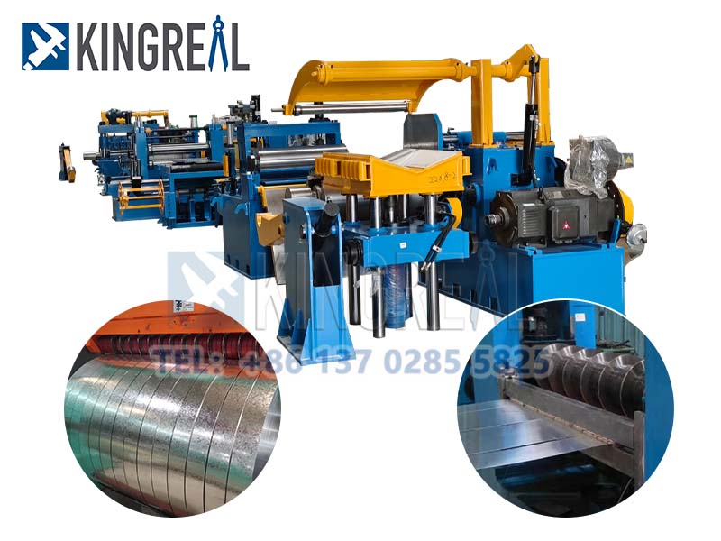
The Coil Slitting Machine is mainly used for slitting metal coils, which is a mainstream product in the metal cutting equipment market. It is commonly seen in the market and is used to slit materials such as strip steel, stainless steel, and copper. It is primarily used by steel processing manufacturers (steel market operators, rolling mill manufacturers, electrical industry, automotive industry, stamping parts, etc.).
.jpg)
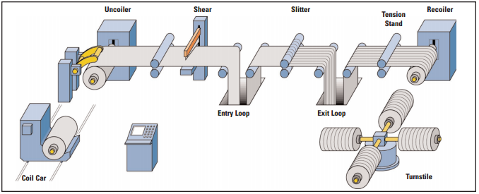
Structure and Functions of the Coil Slitter:
1. Material Storage Table: Used to store raw materials for processing, also known as the raw material standby area, typically customized with 1-2 units.
2. Coil Transport Trolley: Transports raw materials from the storage table to the uncoiler and feeds them into the uncoiling drum through functions such as lifting, lowering, and moving forward and backward. It is usually operated manually or visually but can also be made fully automatic with a “V” plane or roller plane.
3. Uncoiler: Typically a single cantilever type. If the material is heavy, auxiliary supports may be added at the end of the uncoiling drum. The uncoiler base usually has a function to move forward and backward parallel to the machine, enabling effective and rapid centering of the material. It is generally operated visually or with rear movement but can be made fully automatic for centering, though this incurs higher costs.
4. Feeding, Leveling, and Edge Trim Cutting:
- Feeding Rolls: Usually equipped with hydraulic, pneumatic, or electric lifting devices.
- Leveling Machine: Generally uses electric lifting and worm gear structures to ensure stability in lifting and positioning.
- Edge Trim Cutting: Typically uses hydraulic shears to ensure that the material enters the disc shear with a flat end. The drive is usually provided by a variable speed motor to ensure smooth and synchronized line speed.
5. Loop Pit: Also known as the raw material storage buffer pit, usually 2-4 meters deep and 3-4 meters long. It serves as a buffer device to match the speeds of the feeding and coil slitting machines. It typically uses hydraulic or electric lifting platforms to feed materials into the feeding and side guiding devices. The transition platform usually uses rollers and scratch-resistant materials for smooth material contact.
6. Side Guiding and Clamping Devices: Side guiding ensures lateral positioning of the material during rapid movement. It usually employs vertical roller or plate structures to prevent edge running and ensure proper cutting width. Clamping devices generally use dual rollers to ensure material flatness before cutting.
7. Disc Shear: Also known as a coil slitter, it is the core device of the production line. It uses different combinations of blades and spacers to cut materials into various widths. High precision is required for the coil slitting knife shaft, as longitudinal runout, lateral deviation, and mechanical strength affect the precision of the coil slitting product. The accuracy of auxiliary components like circular blades and spacers also affects the product‘s precision and production efficiency. Material rejection can be done using rubber rings or pressing plates, with blade and spacer positioning achieved through nuts or more expensive hydraulic axis locks.
8. Transition Platform: This device transfers the cut product to the finished product loop pit. It must be able to lift freely near the disc shear for blade arrangement and quality assessment. Fixed parts have tail material pressing plates to prevent products from falling into the loop pit and causing tangling.
9. Edge Scrap Recoiler: The edge scrap recoiler uses a disc-style collection device to wind up edge scrap into bundles for storage and transportation. It generally includes screw-type or cam-link guiding devices, with drive provided by variable-speed motors and tension control systems, along with emergency brakes. It can be equipped with manual or automatic unloading options.
10. Finished Product Buffer Pit: Approximately 3-4 meters long and 4-7 meters deep, depending on material thickness, number of slits, and coil diameter. The buffer pit accommodates variations in product length due to thickness tolerance and tension inconsistencies during production. It serves to buffer speed and store product volume.
11. Front Separator Device: This device pre-separates products before they enter the tensioning station, preventing overlapping or stacking when under tension. It typically consists of two separation positioning and anti-jump pressing rollers, with a liftable separation shaft to prevent plastic deformation of the material due to the pressing rollers. The separation shaft is mounted on movable guides for easy adjustment.
12. Tensioning Station:
- Traditional Tension Station: Suitable for materials with surface resistance to scratches or non-mirror finishes. It is effective for various materials but may cause scratches if not protected by a surface film.
- Belt Tension Station: Generates tension through the sliding resistance difference between the belt and inner tension roller, suitable for bright mirror-finish surfaces. It may damage certain thicknesses and narrow strips.
- Roller Tension Station: Suitable for thin sheets (0.5mm or less), generating tension through roller resistance or speed differences. It may cause damage to thicker materials.
Traditional tensioning stations are favored for their even tension, simple adjustment, and maintenance, despite potential surface scratching that can be mitigated with surface films.
13. Feeding and Cutting Bed: The feeding machine provides power for material entry into the recoiler or feeds materials cut by the coil slitting bed into the recoiler. It generally uses pneumatic, hydraulic, or electric drives. The cutting bed typically uses hydraulic shears for cross-cutting and includes product guiding and flattening rollers.
14. Recoiler: Also known as the finished product re-coiling machine, it rewinds slit products into coils. It features expandable and contractible structures for smooth product exit and includes separation devices to prevent overlapping and ensure even winding. It uses hydraulic lifting with balancing valves for automatic adjustment as the coil grows larger, with hydraulic push plates for smooth product release. For heavy coils, auxiliary supports are provided. The drive motor uses a constant power DC motor to ensure adequate winding force and prevent cone-shaped coils, with rapid braking to avoid tearing.
15. Unloading Trolley: Uses hydraulic lifting and a “V” structure design to ensure coil stability. It uses hydraulic or electric drive to transport the finished coil to a convenient lifting location, with anti-tipping rollers to prevent coil overturning.
16. Electrical Control Cabinet, Operation Console, Electric, Hydraulic, and Pneumatic Stations.
This article provides a detailed introduction to the structure and functions of the coil slitter. We hope it is helpful to you. If you have any further questions or need more information, please continue to follow KINGREAL!


 +86-137 0285 5825
  sales@kingreal.org
 jet-clima